Configuring Hitachi HD44780 Character LCD
Oftentimes we need to connect a Non-TFT LCD to a Embedded Linux board and that is completely normal. Why spend a lot of money when you can just use a relatively cheaper part. Also many a times we only need a few bits of information. A Character LCD is perfect for this.
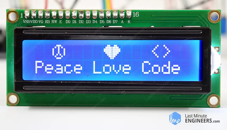
Fig 1 - Character LCD
There are many tutorials online that can make connecting a character LCD to Raspberry PI and they use an userspace driver to make the LCD work. But what if want to:
- Use a different/Custom board. RPI is not favorable to mass production.
- Use a kernel driver.
In that case, follow along. The STM32F469 discovery board already includes a Arduino connector and a i2C connector.
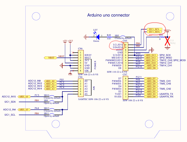
Fig 2 - I2C connector on STM32F469 Discovery board
I use the I2C based expander so that I can save GPIOs. So lets first connect the GPIO expander to the LCD.
Once that is connected, plug it to the board using Female to Female jumper wire.
Enabling I2C Support
First things first, we need to enable i2C support. Remember to do so, we need to issue:
$ cd buildroot
$ make linux-menuconfig
Go to drivers->i2C Support
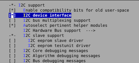
Fig 3 - Enable i2C support in Linux kernel
This is the overall i2C support. We also need support for a specific driver. This is for STM32F4.
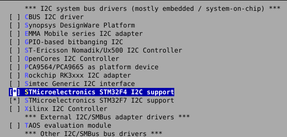
Fig 4 - Enable i2C Hardware support in Linux kernel
There is something called as an auxillary display in linux kernel. These are away from mainstream devices such as
- Character LCDs (HD44780 16×2, 20×4)
- Small I²C/SPI OLEDs (SSD1306, SH1106)
They usually:
- have no framebuffer
- support text or very limited graphics
- are not driven by DRM/KMS
- are optional
How to use them is shown later on.
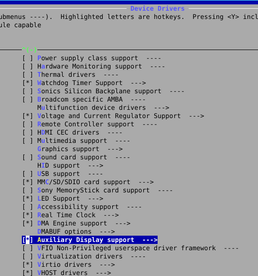
Fig 5 - Enable AUX display support in Linux kernel
Now we need to also enable a certain type of Aux display which in our case is HD44780 16x2 character display.
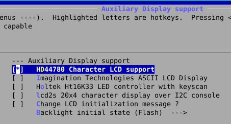
Fig 6 - Enable HD44780 display support in Linux kernel
Now the display in our example is not using a direct HD44780 connected to the board over GPIO. Instead there is a GPIO expander that is I2C based. GPIO expander chips do the same exact thing. They expand the GPIO over I2C bus. The host writes each gpio as a single transaction to write to the GPIO or read all GPIO in a single transaction.
Now once that is enabled, a specific type of GPIO expander is needed. PCF857x in our case it is PCF8574. Enable that support. To go a GPIO expander: go to Device Drivers->GPIO Support->I2C GPIO expander->PCF857X..
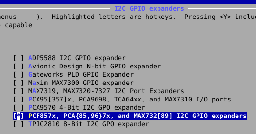
Fig 7 - Enable GPIO expander support in Linux kernel
You may have to zoom in but the final config must look like this.
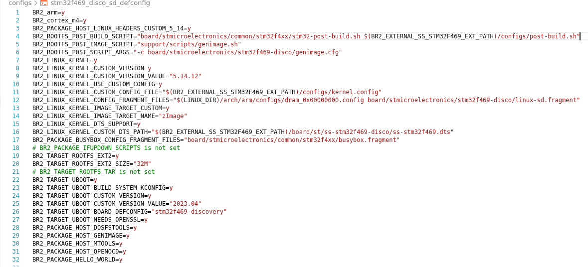
Fig 8 - Final Config
Buildroot External Device Tree
Its now time to start using our own buildroot configuration. We add the configuration to our own buildroot-external config folder.
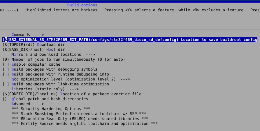
Fig 9 - Buildroot config
When we save the config it is saved here.
$ make savedefconfig
Its better to use our own post build scripts that run when we compile the who buildroot linux.
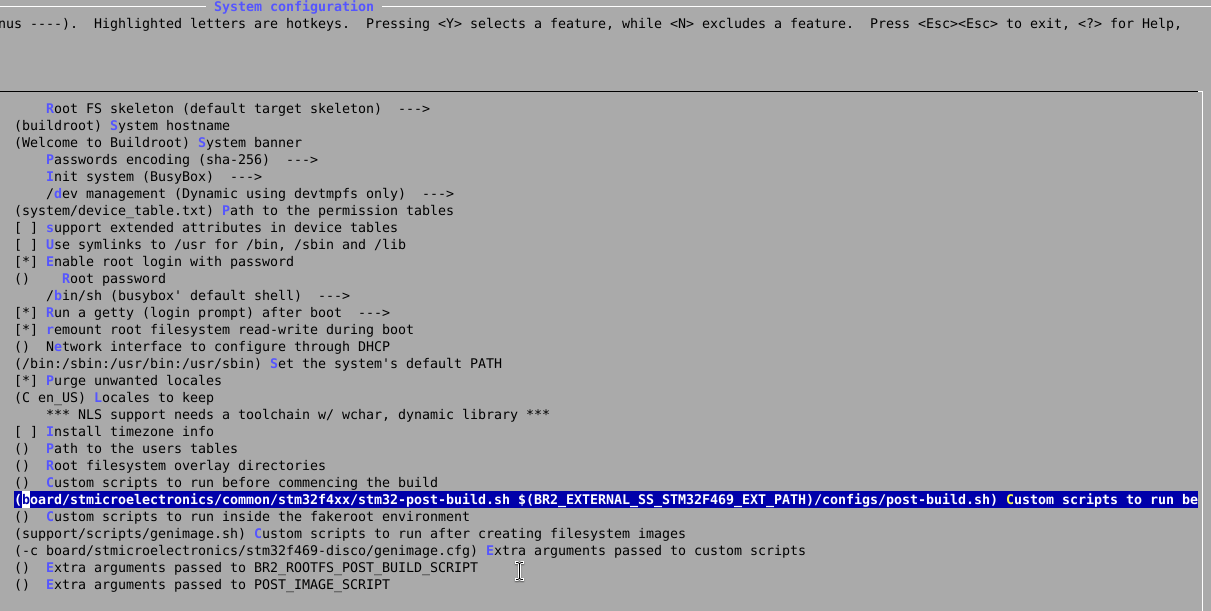
Fig 10 - post scripts
I have also changed the last script that runs inorder to make sure that the desired name of device tree is used.
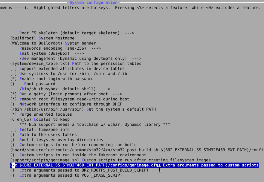
Fig 11 - GenImage scripts
Device Tree
Although support for a particular device is enabled, the kernel still wont know what GPIO it is attached to, what I2C pins are used etc… To do we need to write that stuff in device tree.
This is the device tree that I have put in board/st/ folder
/*
* Copyright 2016 - Lee Jones <lee.jones@linaro.org>
*
* This file is dual-licensed: you can use it either under the terms
* of the GPL or the X11 license, at your option. Note that this dual
* licensing only applies to this file, and not this project as a
* whole.
*
* a) This file is free software; you can redistribute it and/or
* modify it under the terms of the GNU General Public License as
* published by the Free Software Foundation; either version 2 of the
* License, or (at your option) any later version.
*
* This file is distributed in the hope that it will be useful,
* but WITHOUT ANY WARRANTY; without even the implied warranty of
* MERCHANTABILITY or FITNESS FOR A PARTICULAR PURPOSE. See the
* GNU General Public License for more details.
*
* You should have received a copy of the GNU General Public
* License along with this file; if not, write to the Free
* Software Foundation, Inc., 51 Franklin St, Fifth Floor, Boston,
* MA 02110-1301 USA
*
* Or, alternatively,
*
* b) Permission is hereby granted, free of charge, to any person
* obtaining a copy of this software and associated documentation
* files (the "Software"), to deal in the Software without
* restriction, including without limitation the rights to use,
* copy, modify, merge, publish, distribute, sublicense, and/or
* sell copies of the Software, and to permit persons to whom the
* Software is furnished to do so, subject to the following
* conditions:
*
* The above copyright notice and this permission notice shall be
* included in all copies or substantial portions of the Software.
*
* THE SOFTWARE IS PROVIDED "AS IS", WITHOUT WARRANTY OF ANY KIND,
* EXPRESS OR IMPLIED, INCLUDING BUT NOT LIMITED TO THE WARRANTIES
* OF MERCHANTABILITY, FITNESS FOR A PARTICULAR PURPOSE AND
* NONINFRINGEMENT. IN NO EVENT SHALL THE AUTHORS OR COPYRIGHT
* HOLDERS BE LIABLE FOR ANY CLAIM, DAMAGES OR OTHER LIABILITY,
* WHETHER IN AN ACTION OF CONTRACT, TORT OR OTHERWISE, ARISING
* FROM, OUT OF OR IN CONNECTION WITH THE SOFTWARE OR THE USE OR
* OTHER DEALINGS IN THE SOFTWARE.
*/
/dts-v1/;
#include "stm32f469.dtsi"
#include "stm32f469-pinctrl.dtsi"
#include <dt-bindings/gpio/gpio.h>
#include <dt-bindings/input/input.h>
/ {
model = "STMicroelectronics STM32F469i-DISCO board";
compatible = "st,stm32f469i-disco", "st,stm32f469";
chosen {
bootargs = "root=/dev/ram";
stdout-path = "serial0:115200n8";
};
memory@00000000 {
device_type = "memory";
reg = <0x00000000 0x1000000>;
};
aliases {
serial0 = &usart3;
};
mmc_vcard: mmc_vcard {
compatible = "regulator-fixed";
regulator-name = "mmc_vcard";
regulator-min-microvolt = <3300000>;
regulator-max-microvolt = <3300000>;
};
vdd_dsi: vdd-dsi {
compatible = "regulator-fixed";
regulator-name = "vdd_dsi";
regulator-min-microvolt = <3300000>;
regulator-max-microvolt = <3300000>;
};
soc {
dma-ranges = <0xc0000000 0x0 0x10000000>;
};
leds {
compatible = "gpio-leds";
led-green {
gpios = <&gpiog 6 GPIO_ACTIVE_LOW>;
linux,default-trigger = "heartbeat";
};
led-orange {
gpios = <&gpiod 4 GPIO_ACTIVE_LOW>;
};
led-red {
gpios = <&gpiod 5 GPIO_ACTIVE_LOW>;
};
led-blue {
gpios = <&gpiok 3 GPIO_ACTIVE_LOW>;
};
};
gpio-keys {
compatible = "gpio-keys";
autorepeat;
button-0 {
label = "User";
linux,code = <KEY_WAKEUP>;
gpios = <&gpioa 0 GPIO_ACTIVE_HIGH>;
};
};
/* This turns on vbus for otg for host mode (dwc2) */
vcc5v_otg: vcc5v-otg-regulator {
compatible = "regulator-fixed";
enable-active-high;
gpio = <&gpiob 2 GPIO_ACTIVE_HIGH>;
regulator-name = "vcc5_host1";
regulator-always-on;
};
auxdisplay: auxdisplay {
		compatible = "hit,hd44780";
		reg = <0>;

		display-height-chars = <2>;
		display-width-chars = <16>;

		data-gpios = <&pcf8574 4 GPIO_ACTIVE_HIGH>,  <&pcf8574 5 GPIO_ACTIVE_HIGH>,  <&pcf8574 6 GPIO_ACTIVE_HIGH>, <&pcf8574 7 GPIO_ACTIVE_HIGH>;

		rs-gpios = <&pcf8574 0 GPIO_ACTIVE_HIGH>;
		rw-gpios =  <&pcf8574 1 GPIO_ACTIVE_HIGH>;
		enable-gpios = <&pcf8574 2 GPIO_ACTIVE_HIGH>;
		//backlight-gpios = <&pcf8574 6 GPIO_ACTIVE_HIGH>;
	};
};
&rcc {
compatible = "st,stm32f469-rcc", "st,stm32f42xx-rcc", "st,stm32-rcc";
};
&clk_hse {
clock-frequency = <8000000>;
};
&dsi {
#address-cells = <1>;
#size-cells = <0>;
status = "okay";
ports {
#address-cells = <1>;
#size-cells = <0>;
port@0 {
reg = <0>;
dsi_in: endpoint {
remote-endpoint = <<dc_out_dsi>;
};
};
port@1 {
reg = <1>;
dsi_out: endpoint {
remote-endpoint = <&dsi_panel_in>;
};
};
};
panel-dsi@0 {
compatible = "orisetech,otm8009a";
reg = <0>; /* dsi virtual channel (0..3) */
reset-gpios = <&gpioh 7 GPIO_ACTIVE_LOW>;
power-supply = <&vdd_dsi>;
status = "okay";
port {
dsi_panel_in: endpoint {
remote-endpoint = <&dsi_out>;
};
};
};
};
<dc {
status = "okay";
port {
ltdc_out_dsi: endpoint@0 {
remote-endpoint = <&dsi_in>;
};
};
};
&rtc {
status = "okay";
};
&timers1 {
status = "okay";
pwm {
pinctrl-0 = <&pwm1_pins>;
pinctrl-names = "default";
status = "okay";
};
timer@0 {
status = "okay";
};
};
&timers3 {
status = "okay";
pwm {
pinctrl-0 = <&pwm3_pins>;
pinctrl-names = "default";
status = "okay";
};
timer@2 {
status = "okay";
};
};
&sdio {
status = "okay";
vmmc-supply = <&mmc_vcard>;
cd-gpios = <&gpiog 2 GPIO_ACTIVE_LOW>;
broken-cd;
pinctrl-names = "default", "opendrain";
pinctrl-0 = <&sdio_pins>;
pinctrl-1 = <&sdio_pins_od>;
bus-width = <4>;
};
&usart3 {
pinctrl-0 = <&usart3_pins_a>;
pinctrl-names = "default";
status = "okay";
};
&usbotg_fs {
dr_mode = "host";
pinctrl-0 = <&usbotg_fs_pins_a>;
pinctrl-names = "default";
status = "okay";
};
/* Kernel mapping in the actual device tree seems invalid. So i am
putting based on the actual STM32F469 board */
&pinctrl {
    i2c1_pins_pb8pb9: i2c1-pb8pb9 {
        pins {
            pinmux = <STM32_PINMUX('B', 9, AF4)>, /* SDA */
                     <STM32_PINMUX('B', 8, AF4)>; /* SCL */
            bias-disable;
            drive-open-drain;
            slew-rate = <3>;
        };
    };
};

&i2c1 {
    status = "okay";
    clock-frequency = <100000>;
    pinctrl-names = "default";
    pinctrl-0 = <&i2c1_pins_pb8pb9>; /* Defined in stm32f4-pinctrl.dtsi */

    pcf8574: gpio@27 {
        compatible = "nxp,pcf8574";
        reg = <0x27>;
        gpio-controller;
        #gpio-cells = <2>;
    };
};
This device tree is taken from stm32f469.dts and i have added the following:
The Aux display
auxdisplay: auxdisplay {
compatible = "hit,hd44780";
reg = <0>;
display-height-chars = <2>;
display-width-chars = <16>;
data-gpios = <&pcf8574 4 GPIO_ACTIVE_HIGH>, <&pcf8574 5 GPIO_ACTIVE_HIGH>, <&pcf8574 6 GPIO_ACTIVE_HIGH>, <&pcf8574 7 GPIO_ACTIVE_HIGH>;
rs-gpios = <&pcf8574 0 GPIO_ACTIVE_HIGH>;
rw-gpios = <&pcf8574 1 GPIO_ACTIVE_HIGH>;
enable-gpios = <&pcf8574 2 GPIO_ACTIVE_HIGH>;
//backlight-gpios = <&pcf8574 6 GPIO_ACTIVE_HIGH>;
};
corresponding i2c pins and support for PCF8574 device as a slave device.
/* Kernel mapping in the actual device tree seems invalid. So i am
putting based on the actual STM32F469 board */
&pinctrl {
i2c1_pins_pb8pb9: i2c1-pb8pb9 {
pins {
pinmux = <STM32_PINMUX('B', 9, AF4)>, /* SDA */
<STM32_PINMUX('B', 8, AF4)>; /* SCL */
bias-disable;
drive-open-drain;
slew-rate = <3>;
};
};
};
&i2c1 {
status = "okay";
clock-frequency = <100000>;
pinctrl-names = "default";
pinctrl-0 = <&i2c1_pins_pb8pb9>; /* Defined in stm32f4-pinctrl.dtsi */
pcf8574: gpio@27 {
compatible = "nxp,pcf8574";
reg = <0x27>;
gpio-controller;
#gpio-cells = <2>;
};
};
Once this is in place, the whole build can be done again and copied over.
$ make
Copy the sdcard.img to the SD card and boot it.
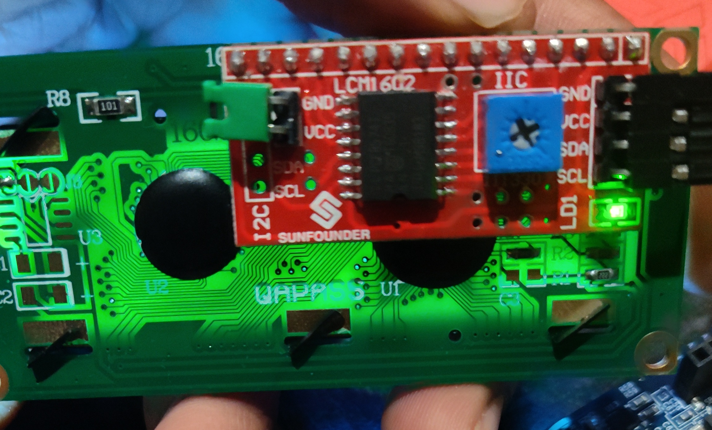
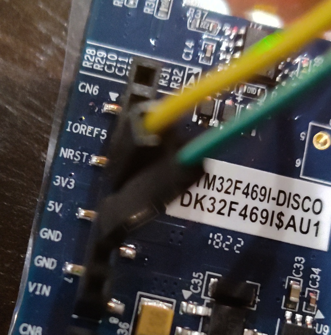

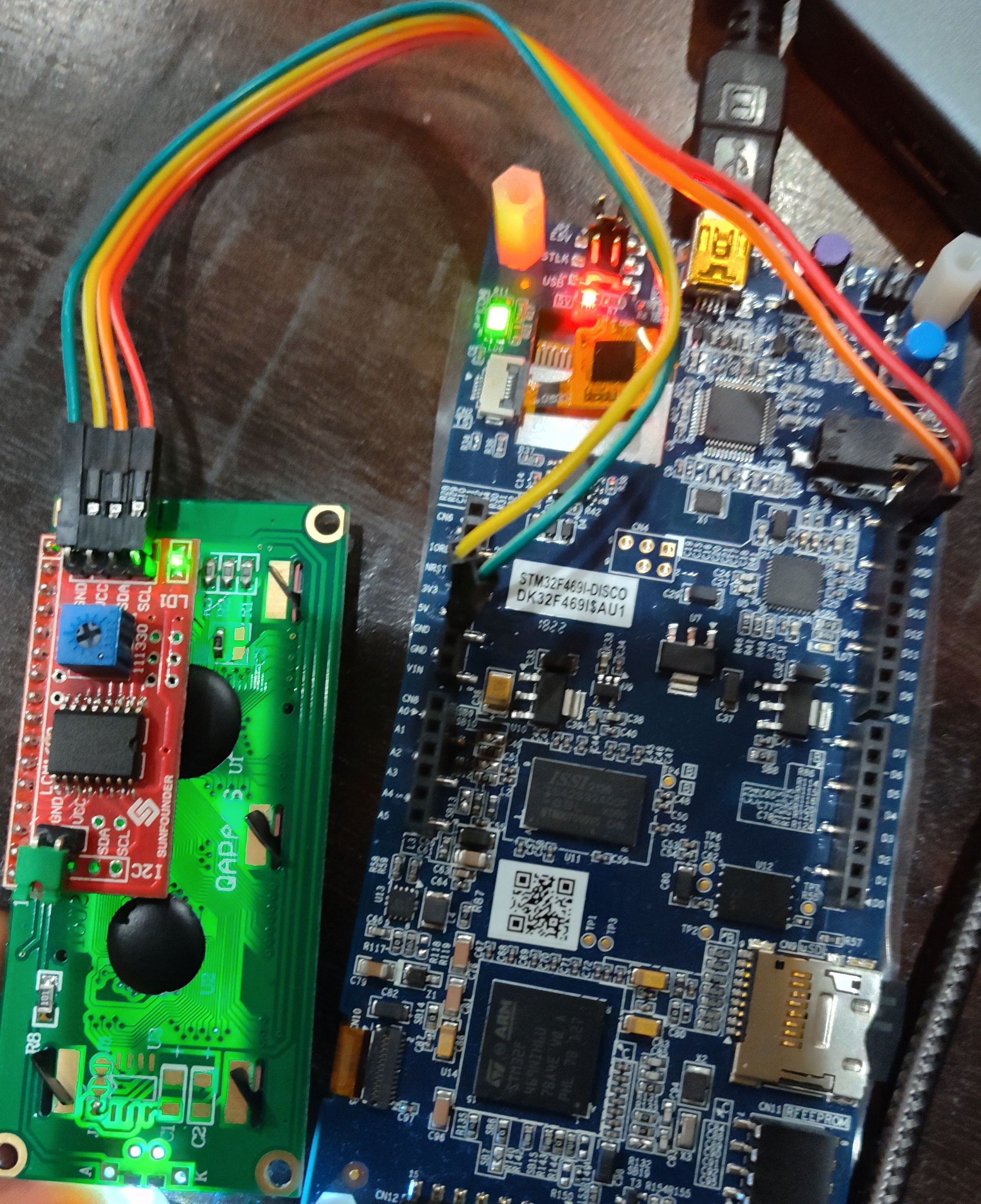
Fig 12 - Overall connections
It is quite satisfying to see linux boot
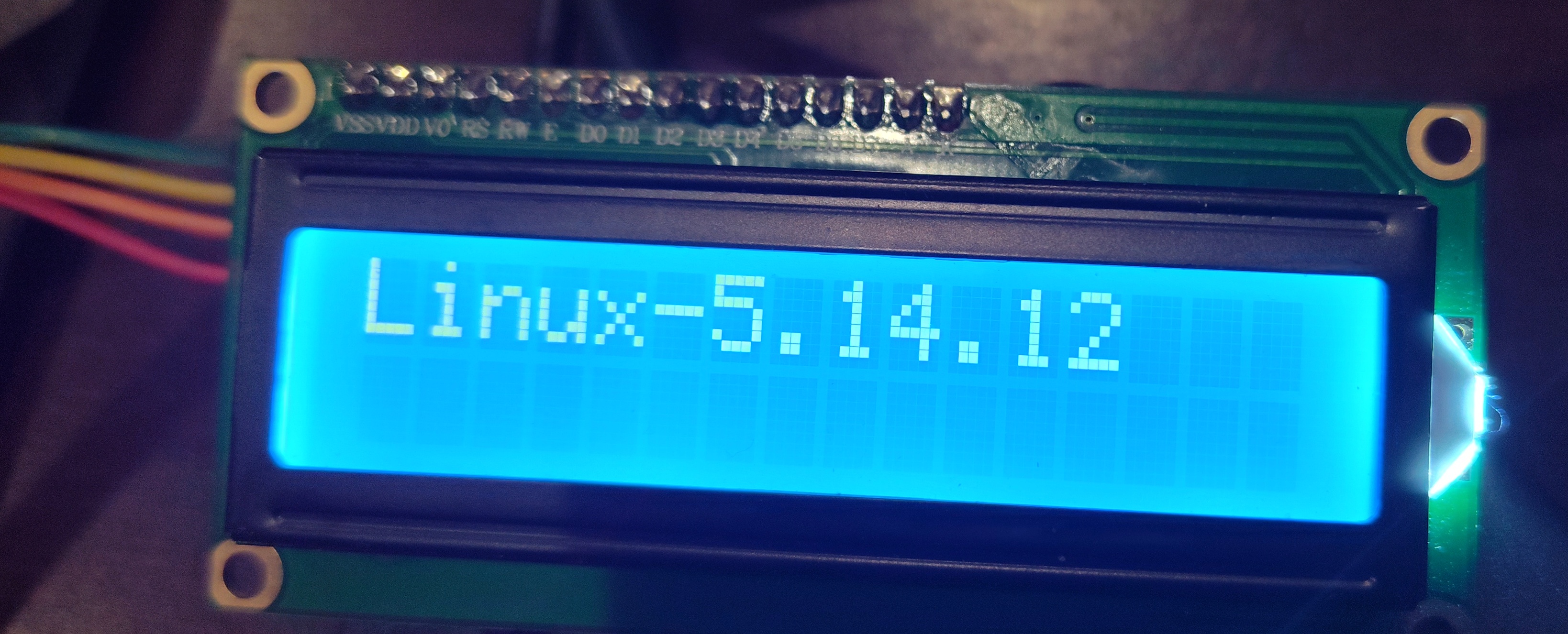
Fig 13 - Linux booting
Using LCD
Now that the lcd is ready. It shows up as /dev/lcd
To write hello world
echo "Hello World" > /dev/lcd
Clear the display
echo -e "\f" > /dev/lcd
To write 2 lines
printf "Line 1\nLine 2" > /dev/lcd
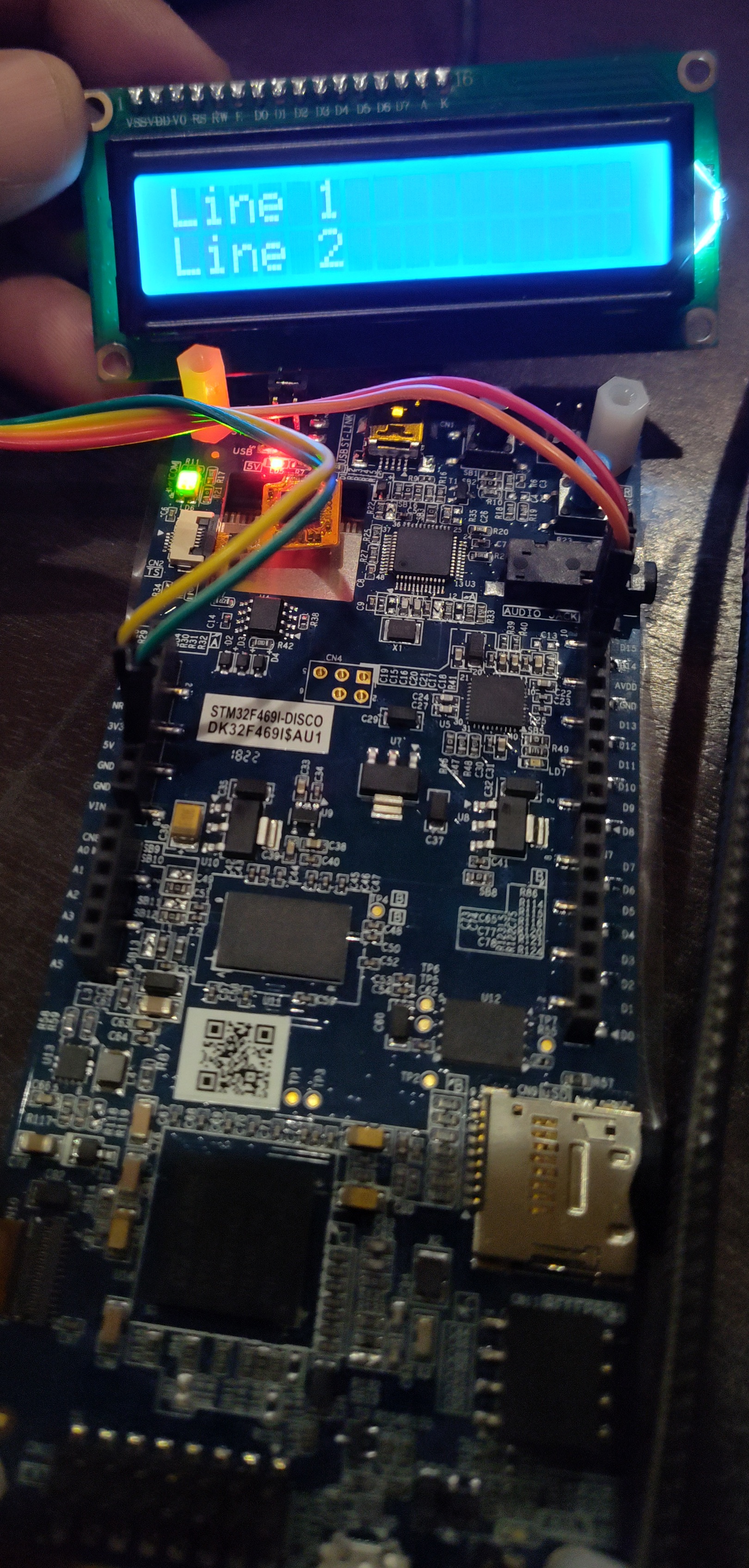
Fig 14 - 2 lines on LCD